Radiation Protection
Home > Radiation Protection and Quality Assurance > Radiation Protection
Eight; 8 questions out of the 35 questions in the Radiation Protection and Quality Assurance content area come from the Radiation Protection sub-topic.
Can we please get your advice on this one question?
Fundamental Principles of radiation are significant to maintain the radiation protection. The fundamental principles are,
- Justification
- Optimization
- Dose & Dose limits
These principles should be followed by each and every person who is directly or indirectly in the way of radiation protection. The principles are explained below.
Justification:
No use of ionizing radiation is justified if there is no benefit. All applications must be justified. This implies all, even the smallest exposures are potentially harmful and the risk must be offset by a benefit. Justification need to evaluate the benefits of radiation and doing in easy way especially in the case of radiotherapy. Assessment of the risks requires the knowledge of the dose received by persons.
Optimization:
Optimization of the procedure is crucial phenomenon. When radiation is to be used then the exposure should be optimized to minimize any possibility of detriment. Optimization is “doing the best you can under the prevailing conditions”. Need to be familiar with techniques and options to optimize the application of ionizing radiation - this is really the main objective of the present course.
Principle of Optimization:
AS Low As Reasonably Achievable (ALARA) is the main principle of optimization. Whatever be the procedure the optimization should be there to minimize the risk of the effects of radiation. Optimization can be divided into two types one is optimizing the tumor and normal structures and another one is optimizing the protection of Occupational workers, patients, and Public’s.
Both the justification and optimization are include in a part of strategies when handling the potential situations or procedure.
Dose & Dose limits:
Dose limits are one of the three principles of protection as introduced by ICRP and BSS. Fixed dose limits are recommended by ICRP and often enforced by a national regulatory body. Dose constraints are used in an optimization process to guide Treatment planning. Constraints and the importance thereof may be subject to change to achieve the optimum solution to a problem.
“No dose limitation for medical exposure of the patient - it is always assumed that the benefits for the patient outweigh the risks”
“Limits need to be applied for public and occupational exposures."
Questions:
- What is the principle of optimization?
- Distance
- Time
- Shielding
- ALARA
2. Dose limits are applied only for,
- Patients
- Public and Occupational
- Non radiation workers
- All
Answer:
- ALARA
- Public and Occupational
References:
- www.ehs.ucsc.edu
- International Basic Safety Standards for protection against Ionizing Radiation and for the Safety of Radiation Sources. Safety Series:115
- ICRU History, policies and Procedures
- IAEA Training material on Radiation Protection in Radiotherapy.
ALARA
ALARA is an acronym for As Low As Reasonably Achievable. This term is based on the belief that exposure to certain agents could cause potential effects. The concept also implies that there is a relationship between the amount of exposure and the possibility of an effect. There is a risk involved in receiving the exposure. The basis for the ALARA philosophy is quite simple; if you reduce your exposure to certain agents, you reduce the potential risk of an unwanted effect. This basic method to achieve the ALARA principle is Time, Distance, and Shielding. The ALARA philosophy is based on the assumption that exposure to radiation poses a risk. The cautious assumption that a proportional relationship exists between dose and effect for all doses (non-threshold concept) is the basis for ALARA. There may be some risk associated with any dose. This is also called the linear model of exposure.
Instructions to Radiation workers to achieve ALARA:
Facilities having the equipment producing the radiation or radioactive sources for research or treatment purpose should follow the guidelines to reduce the exposure level to the individual or group who are working in the area.
Points to achieve ALARA:
- When a radiation worker working radiation facility first should wear his Personnel Monitoring device.
- Radiation worker should follow the procedures or directions for particular to minimize exposure to him and also for the patient.
- Peoples other than authorised person to work or handle the radiation source or equipment are strictly banned. It leads potential situations.
- Avoid the unnecessary repetition of diagnostic procedure for particular patient. To avoid this type situation trained persons are allowed to work.
- Especially in nuclear medicine air borne activity and the situation is prone to radiation. Because of that must follow the procedures as it’s given for that work.
- To minimize the exposure pre-planned works should be implemented in all the works associated with radiation.
- Non-radiation workers also should obey for postings and signs of radiation.
- The training programs shall be conducted by Radiological Safety Officer (RSO) to implement these types of works or procedures.
Questions:
- The basic methods to reduce the exposure and to achieve the ALARA is,
- Time
- Distance
- Shielding
- All
Answer:
- All
References:
- www.ncrponline.org
- Radiation Safety Fundamentals Workbook by university of California Santa crug and Environmental Health & Safety.
Basic Methods of Protection
Basic methods of Radiation Protection consist of three strategies Time, Distance, and Shielding. These three methods have been widely used till now to reduce exposure of exposure to individuals, and public. The basic are explained briefly below.
Time:
Time is one of the prime factors to reduce the exposure. Whatever be the radiation more time spends in that area more would be the exposure and vice versa. So, that tries to avoid the spending of more time in the radiation areas.
Points to do minimize exposure:
- The time consuming in some potential situations can be reduce by executing the pre-planned situations and works.
- In Emergency situations the work can be shared by group of people who are eligible to do that work. In this way also exposure will be reduce.
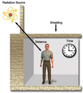
Figure shows the three factors of radiation protection.
Distance:
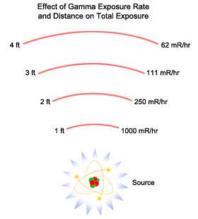
Distance is the second one need to consider when handling or working in the radiation areas. All electromagnetic radiation obeys the Inverse Square Law, means if the distance increases the intensity of the radiation decrease by square of the distance. Expression for inverse square law is,
I1d12 = I2d22
Below figure explains clearly the effect of distance in radiation protection. At 1ft exposure rate 1000mR/hr but, in 2ft it reduces to nearly 1/4th of the earlier one. So that distance should be maintained when handling or working with the radiation sources.
Shielding:
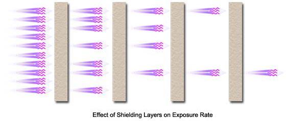
Perhaps to time and distance, shielding is significant one in achieving the radiation protection. Though, time and distance could be factor it is not possible to give enough distance and it is also not practical phenomenon. So, that adequate shielding is required to protect against radiation.
The thickness of the shielding material could vary for different materials. Most common materials used for shielding purpose are listed below.
Name Density (gm/cm2)
- Lead 11.35
- Steel 7.87
- Concrete 2.35
- High Density Concrete 3.8 -4.6
- Polyethylene 0.92
The below figure shows the attenuation by shielding:
Questions:
- Exposure rate measured at 8inches is 30mR/hr. what is the exposure at 2 inches?
- 400 mR/hr
- 480 mR/hr
- 450 mR/hr
- 470 mR/hr
- 11.35 gm/cm
- 11.35 gm/cm2
- 11.00 gm/cm2
- None of these.
Answers:
- 480 mR/hr
- 11.35 gm/cm2
References:
- safety series no. 115
- http://emilms.fema.gov
- www.pubiaea.com
- www.nrc.org
- Basic Radiological Physics by Dr. K. Thayalan
Personnel Monitoring
The aim of personnel monitoring is,
- monitor and control individual doses regularly in order to ensure compliance with the stipulated dose limits
- report and investigate over exposures and recommend necessary remedial measures urgently
- Maintain life time cumulative dose records of the users of the service.
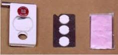
Hence, the radiation received by all the radiation workers during their work should be regularly monitored and a complete up to date record of these doses should be maintained. Personnel monitoring is usually done by employing Film badges, Thermo luminescent dosimeters (TLD) or optically stimulated luminance dosimeter (OSL), and pocket dosimeter.
Film badge:
A film badge is used to measure external individual doses from, x, beta, gamma and thermal neutron radiations. It consists of a film pack loaded in a film holder having suitable metallic filters. The film holder is made up of plastic with stainless steel lining as shown in the figure. It is capable of holding one or more photographic films of size 4cm x 3cm, wrapped inside by a light tight polythene or paper cover. The metallic filters are fixed in both sides of the holder which help to identify the type and energy of incident radiation. There are three types of holder chest, wrist, and head holders.
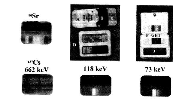
The minimum dose that the film badge can detect is 0.2mSV. The advantage of film badge is permanent record, easily can find the type of radiation, energy and least expensive than other devices.
Thermo Luminescent Dosimeter (TLD):
Film badges has been replaced by TLD’s because of fading at high temperature and humidity, high sensitivity to light, pressure and chemicals, complex dark room procedure.
TLD badges are used currently worldwide instead of film badges. It is based on the phenomenon of thermo luminescence, the emission of light when certain materials are heated after radiation exposure. It is used to measure individual doses from x, beta, and gamma radiations. It gives very reliable results since no fading is observed under extreme climatic conditions. The typical TLD badge consist of plastic cassette in which a nickel coated aluminium card is placed as shown in the below figure. This badge can cover a wide range of doses from10mR to 10,000mR with an accuracy of ±10%.
Optically stimulated luminance dosimeter (OSL):
Dosimeters using stimulated luminance is also available now a days alternative to TLD. The principle of OSL is similar to TLD except the heating. Instead of heating, laser is used to stimulate light emission. Crystalline aluminium oxide activated with carbon (Al2O3:c) is commonly used as OSL dosimeter. It has broad base response and capable of detecting low doses as 10 mSv. The OSL dosimeter can be reuse several times and it can also differentiate between static and dynamic exposures.
Pocket Dosimeters:
Film and TLD will not show accumulated exposure immediately. In addition to the regular film badges, the radiation doses received by the radiation worker can be assessed by wearing a pocket dosimeter, which gives instantaneous radiation exposure. This is very useful in non-routine work, in which the radiation levels vary considerably and may be quite hazardous. The main advantage of pocket dosimeter lies in its ability to provide instant on the spot check of radiation dose received by the personnel. Suitable protective measures can be undertaken immediately to minimize future exposures. The dose can be read off directly by the person during or after any radiation work.
Questions:
- What is the range of measurement of doses in TLD?
- 10mR to 10,000 mR
- 100 mR to 10,000 mR
- 100000 mR
- All
2. What is the advantage of film badge?
- Least expensive
- Permanent record
- Can find the energy, type of the radiation
- All
Answer:
- 10mR to 10,000 mR
- All
References:
- http://hps.org
- www.aerb.gov.in
- Text book of Radiological Physics, by Prof.K. Thayalan.
- The essential physics of medical imaging, second edition by J.T. Bushberg, J.Anthony Siebert, and Edwin leidholdt, JR
Embryo/Foetus Exposure
Embryo or foetus exposure is the significant one when a pregnant radiation worker works in the radiation department or pregnant women undergoing diagnostic procedure or Radiotherapy treatment. Justification and optimization and dose limits are the three principles of radiotherapy. The above mentioned three principles should be following strictly.
Effects of Radiation Exposure in Utero:
- Prenatal doses from most properly done diagnostic procedures present no measurable increase in the risk of prenatal death, malformation, or the impairment of mental development over the background incidence of these entities. Higher doses, such as those involved in therapeutic procedures, can, however, result in significant foetal harm.
- There are radiation related risks throughout pregnancy that are related to the stage of pregnancy and the foetal absorbed dose. Radiation risks are most significant during organogenesis and the early foetal period, somewhat less in the second trimester, and least in the third trimester.
- During the period of ±25 weeks post conception, the central nervous system is particularly sensitive to radiation. Fetal doses in excess of 100mGy may result in a verifiable decrease of IQ. During the same time, foetal doses in the range of 1000 mGy result in a high probability of severe mental retardation. The sensitivity is highest 8±15 weeks post conception. The CNS is less sensitive to these effects at 16±25 weeks of gestational age and rather resistant after that.
- Radiation has been shown to cause leukemia and many types of cancer in both adults and children. Throughout most of pregnancy, the embryo\foetus is assumed to be at the same risk for potential carcinogenic effects of radiation as are children.
Dose limits for pregnant Radiation Worker:
- The pregnant radiation worker has the dose limits of 2mSv
- According to ICRP – 84 foetal doses between 100 – 500 mGy, the decision should be based upon the individual circumstances.
- If the foetal dose exceeds 500mGy the significant foetal damage will occur.
Questions:
- What is the dose limit for foetus or embryo?
- 111mGy
- 100mGy
- 95mGy
- None
Answer:
- 100 mGy
References:
- ICRP report 84
- The text book of radiological physics by Prof. K. Thayalan
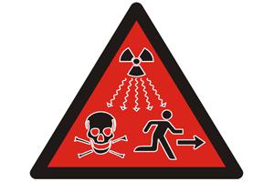
Required postings (signs)
The required postings are mandatory in the places where radiation based jobs are being carried out. The different signs and posters are there for different type of radiation. The signs and posters should not be placed unsuitable places which leads to potential harm to unknown people or patients if enter in that area.
The required postings in the department of radiotherapy, radiology and nuclear medicine should be placed by the Radiological Safety Officer (RSO). Wherever it is needed directions also should mention to prevent the unauthorised access to the radiation source. These posters will guide and alert the people what to do in that area. The required postings for different types of energy and others mentioned below,
The radiation source using places for treatment, diagnostic and research purpose should be paste the below mentioned placard in the entrance of the door for safety of other people. The places are radiotherapy, nuclearmedicine etc.
The required posting for x-ray source usage area is mentioned below. Usually x-rays are used for the diagnostic, radiotherapy treatment, and other areas of interest.
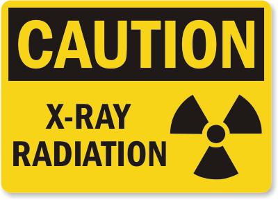
Each and every hospital and diagnostic centres should use the appropriate symbols and posters to guide the patient and other non-radiation workers in that hospital. The Radiological Safety Officer in the hospital or diagnostic centre or research institutes should implement awareness regarding the radiation safety to the non-radiation workers in the particular institution. In that should discuss do’s and don’ts when they are approaching the radiation area. This will help to others indirectly in the radiation protection point of view.
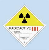
The required packaging Symbols should be use during the transport of radiation source from one place to another place. The required symbols are shown below for better understanding. At any point time misuse of this symbol is an offense under the act of the government. The transport symbol for radiation source or generating equipment is mentioned below.
References:
Area Monitoring Devices
The valuation of radiation levels at different locations in the vicinity of radiation installation is known as area monitoring or radiation survey. These valuations give the details about the integrity of the radiation facility or installation. Instruments used for the above purposes are called radiation survey meters and area monitors. In general, any survey meter or area monitor should consist of two main parts namely. One is a device which detects the radiation and another one is a display system to measure the radiation. Following types of survey meters are generally used for radiation survey and area monitoring.
- Ionization type (air)
- Geiger-Muller (GM) type (Neon and Halogen) and
-
Scintillation detector type [ NaI(Tl), ZnS
(Ag)]
The choice of detector is depend on the type of radiation going to measure, energy, and quantity to be measured. The above mentioned type survey meters are available in portable meters with capable of measuring radiation count rate in mR/hr or R/hr. other devices for area monitoring are Gamma Zone Monitor and door way mounted meters etc.
Ionization Chamber Survey Meter:
Ionization chamber consists of outer cylinder (cathode) coated inside with graphite to make ti conducting and a central electrode (anode) insulated from the chamber wall as shown in the figure. Either air or gas will be used as an interacting medium and a suitable voltage is applied across the electrodes. When the chamber is exposed to radiation, the radiation produces the ionization by interacting with the gas or air inside the chamber. The movement of ions produces an electric current in the outer electronic circuit of the chamber. The strength of this current is proportional to the number of ionization events caused by the energy absorbed in the air chamber and will serve as a measure for find the exposure rate or dose rate.
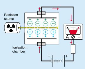
Figure shows the circuit diagram of ion chamber based meters.
Number of ionizations produced in the detector is directly proportional to the energy dissipated in the medium. Therefore, energy discrimination is possible with ionization chamber for heavily charged particles by pulse height analysis. Ionization chambers are used whenever accurate measurements are required. They approximate the condition under which the roentgen is defined. Ion chambers are used to measure outputs of x-ray machine, valuation of radiation levels in brachytherapy, radionuclide therapy patients, and wards and to survey the radioactive material packages.
Ion chamber are capable of monitoring higher radiation exposure rate levels and available in different ranges: 0-5 mR/hr, to 0-50R/hr.
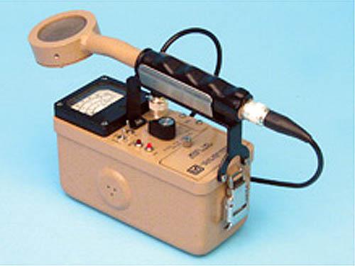
GM Type Survey Meters:
In GM survey meter operating voltage in the range of 500V -1300V applied between the anode and the cathode of a chamber, which is filled with a gas of low electron attachment coefficient (argon and neon). The electrons produced in the chamber will have sufficient energy to produce secondary and tertiary ionization during their acceleration towards anode. This results in an amplification of ionization events in the chamber. This is known as gas avalanche which depends on the nature of gas and the pressure of gas. Hence, the whole wire is covered by a sheath of electrons. The gas amplification is independent of energy and type of radiation. Halogens are used as quenching gas in GM based type Survey meters.
GM meters are pulsed in nature, they should be used only in X or Gamma photons of continuous radiation. They should not be used in X-ray units, which emit pulsed x-ray units such as Linear Accelerators.
Advantages of GM Survey Meter:
- It is very sensitive and useful for monitoring for low level radiation especially in nuclear medicine department.
- GM type instruments rugged and less costly.
- GM type meters are mainly used as radioactive contamination monitor with thin window of 1.5mg/cm2, and large surface area. Contamination monitor is shown below in the diagram.
Disadvantage of GM survey meter is long dead time (100micro sec) and result in loss of 20% of counts in 100,000 cpm measurements. GM survey meters should not be used un high level radiation fields or when accurate exposure rates are required.
Questions:
- What are the quenching gases used in GM based survey meters?
- Halogens
- Inert gases
- Air
- All
2. Energy discrimination is possible in,
- GM based survey meters
- Ion chamber based meters
- Scintillating based meters
- All
Answer:
- Halogens
- ion chamber based meters
References:
- Text book of Radiological Safety, by Prof. K. Thayalan
- www.aerb.gov.in
- http://www.yorkphysics.com
Primary Barrier
Primary barrier is the barrier in which the primary beam of the treatment machine falls (Linac, co-60 units) on it. The thickness of the primary is greater than the other barriers of room. Shielding materials for primary barrier as well as other barriers are same like concrete, lead, and steel etc.
Primary barrier thickness determination:
The required attenuation of the barrier B may be found according to a desired dose constraint that is derived from an occupational or public dose limit. Reference (1) uses the following expression to determine the attenuation required by the barrier.
Where,
P – is the allowed dose per week (Sv/week)outside the barrier.
D – is the distance from the isocentre to the outside of the barrier, in meters.
SAD – Source to Axis Distance in meters
W – is the workload, in Gy/week at 1meter.
U – is the use factor or fraction of time that the beam is likely to be incident on the barrier.
T – is the occupancy factor or the fraction of time that the area outside the barrier is likely to be occupied (mentioned in the table 1)
The thickness of concrete required from attenuation graphs, or by the use of TVLs. The number of TVLs required to produce this attenuation is determined from:

The width of the primary will be calculated as follows,
The primary barrier width is made equal to the maximum to the maximum field size at the barrier plus 1foot (0.305m) on either side to prevent radiation from leaking through the secondary barrier that abuts the primary. Most of the linear accelerator has 40cm x 40cm as maximum field size at one meter from the target.
When the collimator is rotated to 45 degree, the above dimension becomes equal to its diagonal (56.6cm) then the horizontal barrier width (W) required is given by
W = 0.556d+ (0.305 x 2)
Where, d is the distance from the source to the barrier.
Questions:
- Calculate the primary barrier thickness of Co-60 unit. One TVL (density 2350 kg/m3)is 21.8 cm. permissible dose (p) = 0.12mSv/week, distance (d) = 3meter, use factor (U) = 0.25, occupancy factor (T) = 1 and workload of the machine is 384 x 103 mGy/week.
- 1033mm
- 103mm
- 1000mm
- 950mm
Answer:
- 1033mm
References:
- safety Report Series No. 47, IAEA, Vienna:2006
- the Textbook of Radiological Physics, by Prof. K. Thayalan.
- Atomic Energy Regulatory Board lecture notes.
Secondary Barrier
Secondary barriers are the barrier in which the secondary beam will fall on it. However, it is not facing the primary radiation we need to shield against the scattered radiation as well as leakage radiation from the head. Shielding materials used for the secondary barrier is same as the primary barrier only example concrete, lead, and steel etc.
International protocol for the leakage radiation from the head of the linear accelerator must not exceed 0.5% of the primary beam, outside the useful beam at one meter from the path of the electron between the gun and target window and averaged over 100cm3. In the plane of the patient, the leakage must not exceed an average of 0.1% and it would be reasonable to assume this value when determining the required secondary barrier thickness.
The required attenuation (BL) to shield against leakage radiation is as follows:
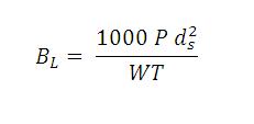
Where,
P - is the design dose limit.
Ds - is the distance from the iso-centre to the point of interest in meter.
W - is the workload.
T – is the occupancy factor.
The use factor for the secondary barrier is always considered as 1 for the determining protection, because of that no need to write in the equation. In this case ds should be measured from the gun end of the wave guide to the point just outside this barrier since this barrier will be subjected to leakage radiation from the vicinity of the gun.
Barrier thickness to shield against scattered radiation:
The required barrier transmission (Bp) needed to shield against radiation scattered by the patient.
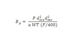
Where,
P, W and T have the same meaning as in the leakage radiation equation.
dsca – is the distance from the radiation source to the patient, in meter
dsec – is the distance from the patient to the point of interest, in meter
a - is the scatter fraction defined at dsca. The scatter primary ratio (a) is dependent on the energy of the X ray beam and the scattering angle. These data re tabulated per 400 cm2 of irradiated field area for Co60, 6, 10, 18, and 24 MV X ray beams.
F – is the field area incident on the patient , in cm2
Scattered radiation from the patient or phantom is usually less than 0.1% of the incident radiation per 0.1 m2 area irradiated. For larger scatter angles, the energy of the scattered radiation will be degraded.
If the thickness required protecting from leakage differs from that required to protect from scatter by less than one TVL, use the greater thickness and add one HVL of shielding material for the energy of the leakage radiation. If the two thicknesses for leakage and scatter protection differ by more than one TVL use the greater thickness.
Questions:
- What will be the thickness of the secondary barrier if the leakage and scattered radiation barrier transmission value differs by one TVL,
- Use the greater thickness and add it one HVL
- Use the greater thickness and add it two HVL
- Use the lesser thickness
- All
Answer:
- Use the greater thickness and add it one HVL
References:
- Safety Report Series no. 47, IAEA, Vienna
- The Textbook of Radiological Physics, by Dr. K. Thayalan.
Home > Radiation Protection and Quality Assurance > Radiation Protection
FREE Infographic What successful people believe. What successful people do
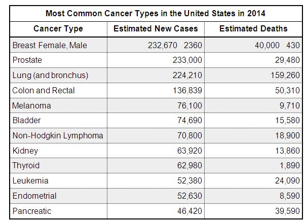
Dictionary of Cancer Terms
Need help understanding a word? Here is an electronic resource that gives meaning to Cancer terms and their usage.

StrengthsFinder 2.0