Treatment Planning
Can we please get your advice on this one question?
- Treatment Techniques
- Fluoroscopic Simulation
- CT Simulation
- Contrast Media
- Simulation Procedure
- Treatment Prescription
- Geometric Parameters
- Dose Calculation
- Types of Devices
- Design Methods and Materials
- Parameters
Treatment Volume Localization > Treatment Techniques
- Critical organs
New radiotherapy techniques allow treating the tumour precisely. In radiotherapy two main streams are there one is External beam therapy and another one is Brachytherapy.
In external beam therapy in turn has different techniques they are,
- Conventional therapy
- 3D Conformal Radiotherapy (3DCRT)
- Intensity Modulated Radiotherapy (IMRT)
- Image Guided Radiotherapy (IGRT)
- Volumetric Modulated ARC Therapy
- Stereotactic Radio surgery / Stereotactic radiotherapy (SRS/SRT)
Indeed, Brachy therapy also has its own different techniques they are,
- Intracavitary Brachytherapy
- InterStitial Brachytherapy
- Surface moulds
- Intracavitary therapy is used when applicators containing radioactive sources can be introduced into body cavities like cervix, lumen etc.,
- Interstitial therapy is indicated when the tumor is well localized (breast, prostrate, cheek etc.,) and can be implanted directly according to accepted rules of distribution.
- Surface molds are used to treat small superficial areas, such as the ear or the lip.
In all these cases, owing to the short treatment distance,
the geometry of source distribution is critical.
Three Dimensional Conformal Radiotherapy (3DCRT):
3DCRT is the superior technique to the conventional radiotherapy, in conventional radiotherapy sparing of normal tissues difficult task and sometimes not possible also. After the introduction of 3DCRT it make us to conform the irregular shape of the tumor with help of Multilevel collimators, customized etc. Indeed, helped to spare the normal tissues in many cases. For doing this technique we should require three dimensional information of anatomy with good treatment planning system.
Intensity modulated radiotherapy (IMRT):
IMRT is a technique which uses linear accelerators to deliver conformal radiation – radiation which is sculpted to the shape of the tumour. IMRT utilises the multi-leaf collimators on a linear accelerator to vary the radiation beam intensity around a target field. The shape of the radiation beams may change hundreds of times during the course of treatment. The intensity of the beams and the direction from which they are delivered also varies. The result is radiation distributed in three dimensions around the tumour, minimizing radiation dose to normal tissue.
Image Guided Radiotherapy (IGRT):
Image-guided radiation therapy (IGRT) is the use of frequent imaging during a course of radiation therapy to improve the precision and accuracy of the delivery of treatment.
In IGRT, machines that deliver radiation, such as a Linac (for x-ray or photon) or cyclotron/synchrotron (for proton), are equipped with imaging technology so that the physician can image the tumour immediately before or even during the time radiation is delivered, while the patient is positioned on the treatment table. Using specialized computer software, these images are then compared to the images taken during simulation. Any necessary adjustments are then made to the patient's position and/or radiation beams in order to more precisely target radiation at the tumour and avoid healthy surrounding tissue.
IGRT is used to treat tumours in areas of the body that are prone to movement, such as the lungs (affected by breathing), liver, and prostate gland, as well tumours located close to critical organs and tissues. It is often used in conjunction with intensity-modulated radiation therapy (IMRT), proton beam therapy, stereotactic radiosurgery, or stereotactic body radiotherapy (SBRT), which are advanced modes of high-precision radiotherapy that utilize computer-controlled x-ray accelerators to deliver precise radiation doses to a malignant tumour or specific areas within the tumour
Volumetric Modulated Arc Therapy:
RapidArc or VMAT is a volumetric arc therapy that delivers a precisely sculpted 3D dose distribution with a single 360-degree rotation of the linear accelerator gantry. It is made possible by a treatment planning algorithm that simultaneously changes three parameters during treatment:
- Rotation speed of the gantry
- Shape of the treatment aperture using the movement of multileaf collimator leaves
- Delivery dose rate.
Volumetric modulated arc
therapy differs from existing techniques like helical IMRT or
intensity-modulated arc therapy (IMAT) because it delivers dose to the whole
volume, rather than slice by slice. And the treatment planning algorithm
ensures the treatment precision, helping to spare normal healthy tissue.
- Questions:
1. 3DCRT is the conformal radiation therapy is it true or false?
- True
- False
2. IMRT stands for
- Intensity Modulated Radiotherapy
- Intensity modulated Arc Therapy
- Intensity Guided Radiotherapy
- Imaging Modified Radiotherapy
3. Advantages of IGRT are,
- Increases the precision delivery
- Taking into account of motion movements
- Conform the position of the patient
- All
Answers:
- True
- Intensity Modulated Radiotherapy
- All
References:
- http://www.radiologyinfo.org
- http://www.royalmarsden.nhs.uk
- http://www.varian.com
- The Physics of Radiation Therapy by F. M. Khan
- Critical organs
Treatment Volume Localization > Fluoroscopic Simulation
- Exposure factors
- Image processing
- Magnification factors
- Contouring
Treatment Volume Localization > CT Simulation
- CT image Acquisition
The demands of modern radiotherapy planning are quite different from those 20 years ago. Clinicians now require to define the target volume more precisely, not just in two dimensions, but also in three dimensions. It has therefore become necessary to visualize anatomy in three dimensions to enable planning to conform the dose around the target volume in order to irradiate the tumour to as high a dose as possible, and saving the normal tissues. In order to achieve this, the following tools are necessary:
- Identification of critical structures using advanced anatomical and functional imaging methods(CT Simulation).
- Visualization of treatment targets with respect to other structures in three dimensions.
- Efficient and accurate outlining of tumour using contouring tools.
- Addition of symmetrical or asymmetrical volumetric margins.
- Beam’s eye view (BEV) of targets and structures.
- Shaping fields around the target.
- Adding beams together.
- Dose volume histogram (DVH) generation.
- Tools for optimizing plans using forward or inverse interactive techniques.
- Export of plan to linear accelerator.
Monitor unit calculations.
Export of digitally reconstructed radiographs, (DDRs — see below) to an image database for on-line assessment of treatment accuracy.
CT Simulation:
An exciting development in the area of simulation is that of converting a CT scanner into a simulator (figure (a)). CT simulation uses a CT scanner to localize the treatment fields on the basis of the patient's CT scans. A computer program, specifically written for simulation, automatically positions the patient couch and the laser cross-hairs to define the scans and the treatment fields. The software (as part of CT scanner or a stand-alone treatment-planning system) provides outlining of external contours, target volumes and critical structures, interactive portal displays and placement, review of multiple treatment plans, and a display of isodose distribution. This process is known as virtual simulation.
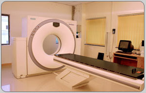
Above figure shows picture of the CT Simulator.
The nomenclature of virtual simulation arises out of the fact that both the patient and the treatment machine are virtual—the patient is represented by CT images and the treatment machine is modeled by its beam geometry and expected dose distribution. The simulation film in this case is a reconstructed image called the DRR (digitally reconstructed radiograph), which has the appearance of a standard 2-D simulation radiograph but is actually generated from CT scan data by mapping average CT values computed along ray lines drawn from a “virtual source” of radiation to the location of a “virtual film.” DRR is essentially a calculated (i.e., computer-generated) port film that serves as a simulation film. The quality of the anatomic image is not as good as the simulation radiograph but it contains additional useful information such as the outlined target area, critical structures, and beam aperture defined by blocks or MLC. A DRR can substitute for a simulator radiograph by itself but it is always preferable to obtain final verification by comparing it with a radiographic simulation film.
Questions:
1. CT simulation leads to
- Accurate delineation of targets
- Three dimensional planning
- Increase in conformality of dose to the target
- All
Answer:
- All
References:
- CT simulation for radiotherapy treatment planning: 1E G A AIRD, MSc, PhD, FIPEM and 2J CONWAY, BSc, PhD, MIPEM, 1Medical Physics Department, Mount Vernon Hospital, Rickmansworth Road, Northwood, Middlesex HA6 2RN and 2Department of Radiotherapy Physics, Weston Park Hospital, Whitham Road, Sheffield S10 2SJ, UK
- The Physics of Radiation Therapy by F. M. Khan
- http://www.aaruni.in/images/c_t_simulation.jpg
- CT image acquisition
Treatment Volume Localization > Contrast Media
- Adverse Reactions
Different tissues within the body attenuate the beam of X-rays to different levels.
The degree of attenuation of an X-ray beam by an element is complex, but one of the major variables is the number of electrons in the path of the beam with which it can interact. The number of electrons in the path of the beam is dependent upon three factors:
- The thickness of the substance being studied
- Its density
- The number of electrons per atom of the element (which is equal to its atomic number)
In a complex mixture of elements, which is of course what we are concerned with in the organs of a patient, the degree of attenuation is particularly influenced by the average of the atomic numbers of all the atoms involved.
Where there is a considerable difference between the densities of two organs, such as between the solid muscle of the heart and the air in the lungs, then the outlines of the structures can be visualised on a radiograph because of the natural contrast that exists. Similarly, if there is a difference between the average atomic numbers of two tissues, such as between soft tissues, which are composed of elements of low atomic number, and bone, which is partly composed of the element calcium, with a rather higher atomic number, then the outlines of the different structures can be seen by natural contrast.
Above figure shows the radiograph taken with the help of contrast
However, if the two organs have similar densities and similar average atomic numbers, then it is not possible to distinguish them on a radiograph, because no natural contrast exists. This situation commonly occurs in diagnostic radiography, so that, for example, it is not possible to identify blood vessels within an organ, or to demonstrate the internal structure of the kidney, without artificially altering one of the factors mentioned earlier.
Two of the factors important in organ contrast can be artificially altered, the density of an organ, and, more usefully, the average atomic number of a structure. The density of a hollow organ can be reduced by filling it with gas or air, providing negative contrast. This is mainly of historical significance, but is still used when, for example, gas is introduced into the stomach or colon during a double-contrast barium examination.
The average atomic number of hollow structure such as a blood vessel
can be increased by filling the cavity with a liquid of much higher average
atomic number (such as iodine containing contrast medium) than that of blood.
In fact this is the principle by which contrast media consist of solutions or
suspensions of non-toxic substances that contain a significant proportion of
elements of high atomic number, usually iodine.
Questions:
1. When compared to soft tissue, bone is clearly visible because of natural contrast (it has high atomic number component)
Answer:
- True
References:
- http://hsc.uwe.ac.uk
- http://content.answcdn.com/main/content/img/oxford/Oxford_Body/019852403x.x-rays.3.jpg
- Adverse Reactions
Treatment Volume Localization > Simulation Procedure
Prescription and Dose Calculation > Treatment Prescription
- Total Tumor Dose
- Fractionation Schedules
- Types of Radiation
- Radiation Energy
- Treatment Volume
Treatment prescription is the important document to know about the patient’s disease, area of tumour, diagnosis, which modality has been planned, treatment energy, planned dose, total number of fractions, and number of fractions received and special instructions to follow during the treatment of the particular patient.
The prescription should consists of following information’s,
- Name of the patient, ID
- Diagnosis
- Treatment site or region
- Treatment modality
- Planned dose and fraction
- Special instructions
- Actual number of fractions received
Name of the Patient:
The correct name of the patient should be written in the prescription. Otherwise it leads to potential effects; this can be avoided b cross checking the patient by asking them to show any other proof of identity (ID).
Diagnosis:
Diagnosis is the most significant part of the prescription because if there is any mistake in writing the diagnosis or if wrongly detected the entire treatment will get continue with false treatment methods. In this regard particular attention should be given during the process. To avoid this doctor recommended doing this part.
Treatment Site or Region:
Treatment site or region needs to be mentioned in the chart for every patient for accurate setup and also to avoid the confusions. Its advised to mention with diagrams are useful for radiation technologist for precise delivery.
Treatment Modality:
Treatment modality is crucial one to mention in the prescription. For example if, the patient is chosen for 3DCRT radical treatment at one phase (but it is not mentioned) after, a long period of gap same patient comes with recurrence and meet another doctor means the situation leads to difficulty in treating the patient. That’s why it should be mentioned in the prescription chart irrespective of the treatment.
Planned dose and fraction:
Planned dose and fraction for each and every tumour may vary. Dose and fractions needs to mention in the prescription chart by the doctor to find the patient’s total dose received by the treatment. In addition to that the fractional dose shall be mentioned for accurate calculation of treatment time. Sometimes the total doses will be delivered in different fractional dose if, it so special attention should be given to that case during calculation and also in reviewing the patient.
Special instructions:
Special instructions if any present in the patient’ treatment, could
be mentioned clearly in the chart. For example wedges, blocks, position of the
patient for the particular treatment (Supine or Prone position etc).
Questions:
1. Pick out the correct one, Prescription should include,
- Details of the treatment site or region
- Details of treatment modality
- Details of planned dose and fractions
- Special instructions
- All
Answer:
1. e) All
References:
- http://www.datadictionary.nhs.uk
- Total Tumor Dose
- Fractionation Schedules
- Types of Radiation
- Radiation Energy
- Treatment Volume
Prescription and Dose Calculation > Geometric Parameters
- Field Size and Shape
- Patient Thickness
Prescription and Dose Calculation > Dose Calculation
- Equivalent Square
- Scatter Factors
- Percentage Depth Dose
- TAR, TMR
- SSD, SAD
- Inverse Square
- Extended Distance Factors
- Wedges
- Off-axis Calculation
- Isodose curves and their characteristics
- Factors for beam modifiers
- Inhomogeneity correction factors
- Machine output data
- Verification and documentation
Dose calculation is a significant step in treating the patient. If, dose calculation failed to do correctly whatever may be the accurate step and other features will go in ineffective. For that the medical physicist or dosimetrist, who are in the place to calculate the dose for the treatment should be precise without any approximation to maintain the quality of radiotherapy.
The formula to calculate the dose per fraction is as follows,
For telecobalt machines:
Treatment time = Tumour dose/Dose rate (min)
For linear accelerators:
Where,
- TD = Tumour Dose
- % DD = Percentage Depth Dose
- Sc (rc) = Collimator Scatter factor
- Sp (r) = Phantom Scatter factor
Dose verification Methods:
Dose verification in external beam radiotherapy and brachy therapy has been done by following methods:
- Radiographic Film
- Ion chamber based pre-treatment verification
- Solid state detectors (diode detectors)
Solid state detectors:
Silicon p–n junction diodes are
often used for relative dosimetry. Their higher sensitivity, instantaneous
response, small size, and ruggedness offer special advantages over ionization
chambers. They are particularly well suited for relative measurements in
electron beams, output constancy checks, and in vivo patient dose monitoring.
Their major limitations as dosimeters include energy dependence in photon
beams, directional dependence, thermal effects, and radiation-induced damage.
Modern diodes for dosimetry have been designed to minimize these effects.
Radiographic Film:
Sensitivity of film depends on the size of emulsion grains (crystals of silver bromide) and the quality and type of radiation.
Slow-speed films (small grain size) such as Kodak XV-2 and Kodak RPM-2 are suitable for relative dosimetry provided their sensitometric curve (also known as H-D curve) is predetermined in comparison with a calibrated ion chamber. Processing conditions must be standardized. Any air pockets between film and its jacket must be eliminated to avoid artifacts.
Optical density is given by log10(I0/It), where I0 is the amount of light incident on film and It is the amount of light transmitted through film. It is measured by a densitometer having a light source and a tiny aperture (~1 mm diameter or less).
Film is well suited for relative
dosimetry of electron beams (shows practically no energy dependence). In photon
beams, however, it shows significant energy dependence and therefore it is used
mostly for portal imaging and quality assurance procedures such as checking
beam alignment, isocentric accuracy, and beam flatness. For measuring dose
distributions, photon energy dependence must be taken into account.
Questions:
1. Dose verification in the radio graphic film will be calculated on the basis of,
- Sensitivity
- Optical density
- Artifacts
- All
2. Solid state detectors are useful in in vivo Dosimetry?
- True
- False
Answers:
- Optical Density
- True
References:
- The Physics of Radiation Therapy by F. M. Khan
- http://iopscience.iop.org
- Equivalent Square
- Scatter Factors
- Percentage Depth Dose
- TAR, TMR
- SSD, SAD
- Inverse Square
- Extended Distance Factors
- Wedges
- Off-axis Calculation
- Isodose curves and their characteristics
- Factors for beam modifiers
- Inhomogeneity correction factors
- Machine output data
- Verification and documentation
Treatment Accessories > Types of Devices
Treatment Accessories > Design Methods and Materials
Treatment Accessories > Parameters
- Image Magnification Factor
FREE Infographic What successful people believe. What successful people do
Dictionary of Cancer Terms
Need help understanding a word? Here is an electronic resource that gives meaning to Cancer terms and their usage.

StrengthsFinder 2.0